Scope
Outline the calculation model for IQM in terms of the physical characteristics and behavior of linear accelerators.
Expected inputs for signal prediction
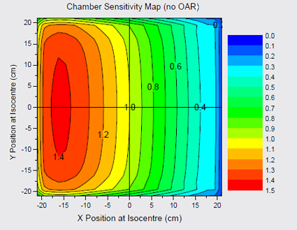
- Chamber characterization
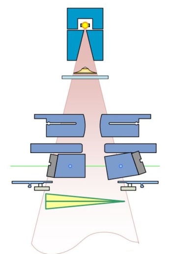
- Treatment unit (Linac) characterization
- Collimation attenuation
- Fluence profiles
- Patient treatment description
- Both static field-in-field and dynamic delivery modes
Fundamentals of signal calculation
- ? = MU setting for segment
- ??? = output change with field size (residual…)
- ???? / ?×?= normalization (electrometer reading)
- ?p, ?s = primary and secondary source intensity matrix
- ?? = fractional contribution from secondary source
- ???? = chamber positional sensitivity matrix
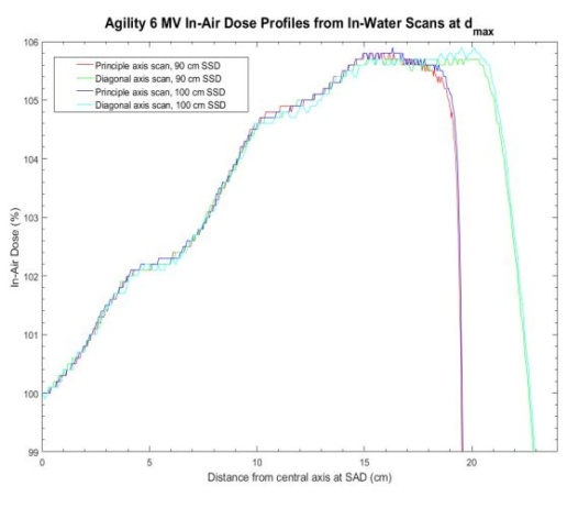
Primary source intensity
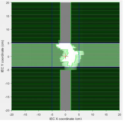
- Starts with open source profile
- Assume radially symmetric intensity profile
- Apply effect of collimation attenuation
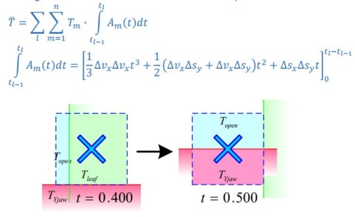
- Works on an area weighted average rather than an intensity to a point
Primary Source Modulation
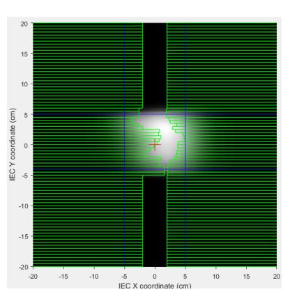
- Area-Weighted Transmission through collimating elements subdivided in regions of transmission and time for each pixel
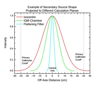
Secondary source
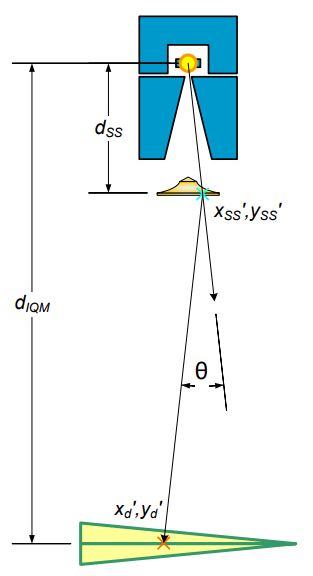
- Extended source geometry
- Positioned at bottom of flattening filter
Secondary source modulation
- More complex geometry
- Non-divergence matched
- Multiple off-axis sources
- Complex element shape shading
- Simplify calculation
- Static “snapshot” calculation
- Sampling point geometry
- Layered collimating element
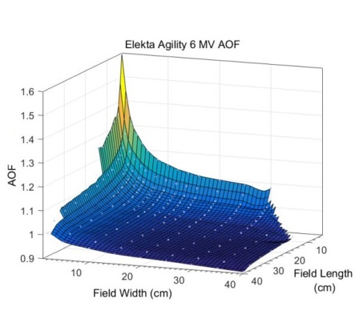
Area output factor characterization
- Captures changes in output due to field size effects
- Derived from a series of rectangular field measurements
- Behaves as a “residual”
- Some effects accounted for byextended source
- Rederived for tweaks in source description & transmission
- Look-up according to average field width, length
This test report is based on a publication created by Princess Margaret Cancer Centre, Toronto (Canada).
Please click on the „Download“ button to download the complete publication.
